Reprogramming A $13 Consumer Wifi Outlet
My condo’s living room is…challenging from a lighting and electric standpoint. It’s about 18’ by 21’, with ceilings that slope down from 22’ at one side to 11’ from the other. There is a light switch in one corner, connected to a single outlet about 8’ away. If I want that light switch to control several lights at various parts of the room, someone would have to run wiring around ~40’ of wall, over doorways and through studs. Another condo is below mine, and the roof is above, so neither attic or basement is an option for running wires. And did I mention that the studs seem to be metal?
Instead, I decided to use relays connected to ESP-8266 wifi-enabled
microcontrollers to control the lights. As a simple proof-of-concept,
I wrote a switch program that would turn on the relay when I made a
GET request to <esp8266 ip>/on and keep it on for 11 seconds, Then
I programmed a “sensor” ESP-8266 to call each of the /on endpoints
every few seconds for as long as it was turned on. I plugged it into
the outlet controlled by the light switch, and connected the lights
to the relays. Now, when I turned on the light switch, it would
activate the sensor chip, which would tell the other chips to turn
on their lights. When I turned off the light switch, the sensor chip
would stop sending “turn on” requests to the others, which would time
out after 11 seconds and turn their lights off. It’s not a sophisticated
system, but it worked. At first I though about using MQTT queues, but then
I decided to use a heartbest from the sensor directly.
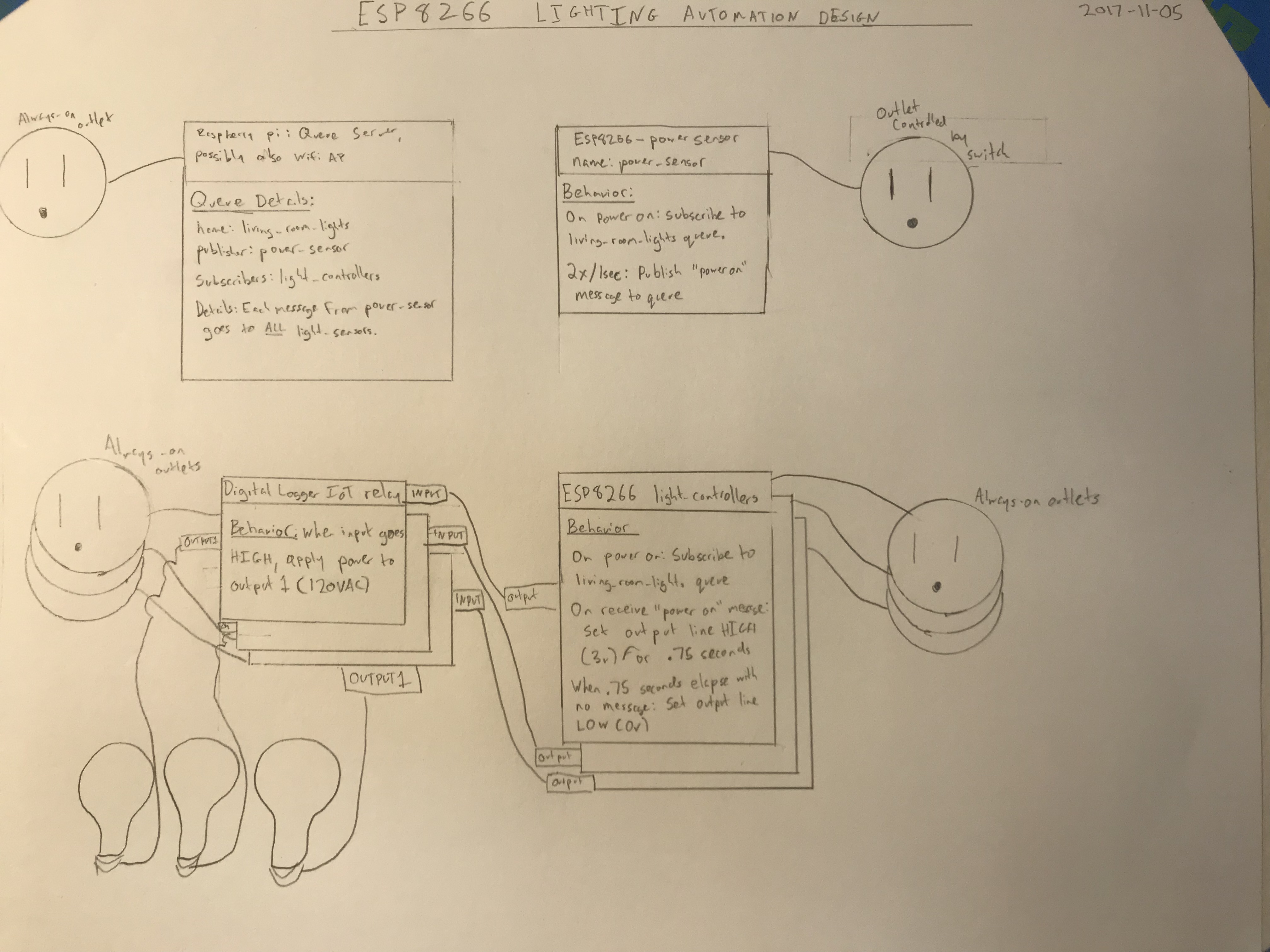
Initial system design
I wasn’t happy with the amount of hardware required. For each outlet I wanted to control, I needed to use one ESP8266 (powered by a wall wart) and one relay (plugged into an always-on outlet. That meant that I needed two plugs, or one full outlet per light. I’ve always avoided building electronics that run on mains power, so I was using nice Digital Loggers relays, which seemed like overkill at $23 each. Adding in an ESP8266 and power supply, the BOM for the project to control 3 lights was around $80. Not to mention it looked bad to have the exposed ESP chips hanging off their power supplies, with tiny wires leading in to the relay inputs.
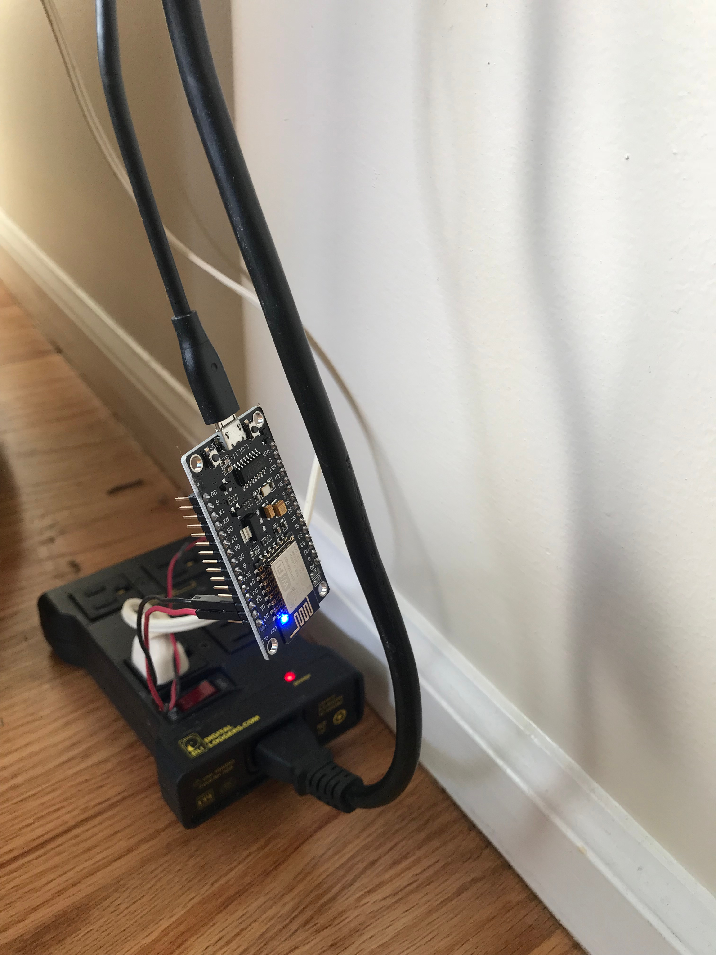
Yuck
What I wanted was a solution that integrated a programmable ESP-8266, power supply, and relay into a nice, clean, UL-listed package that I wouldn’t be embarassed to have plugged in to an outlet in my living room. Fortunately, I wasn’t the first person to have this idea, and a kind soul at hackaday.io had already identified a type of mass-produced, reliable-looking wifi outlet that used an ESP-8266. I picked up two for $24.
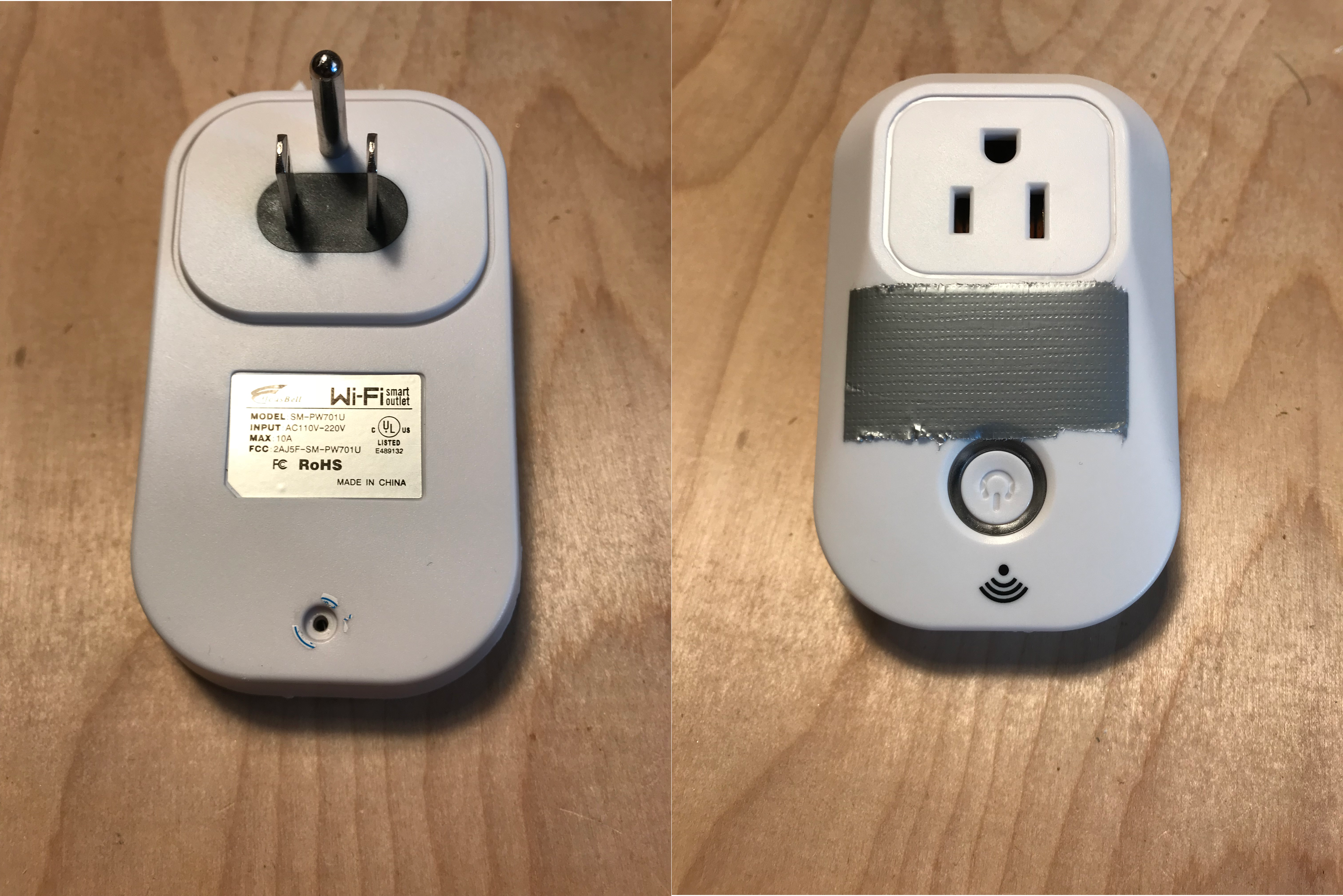
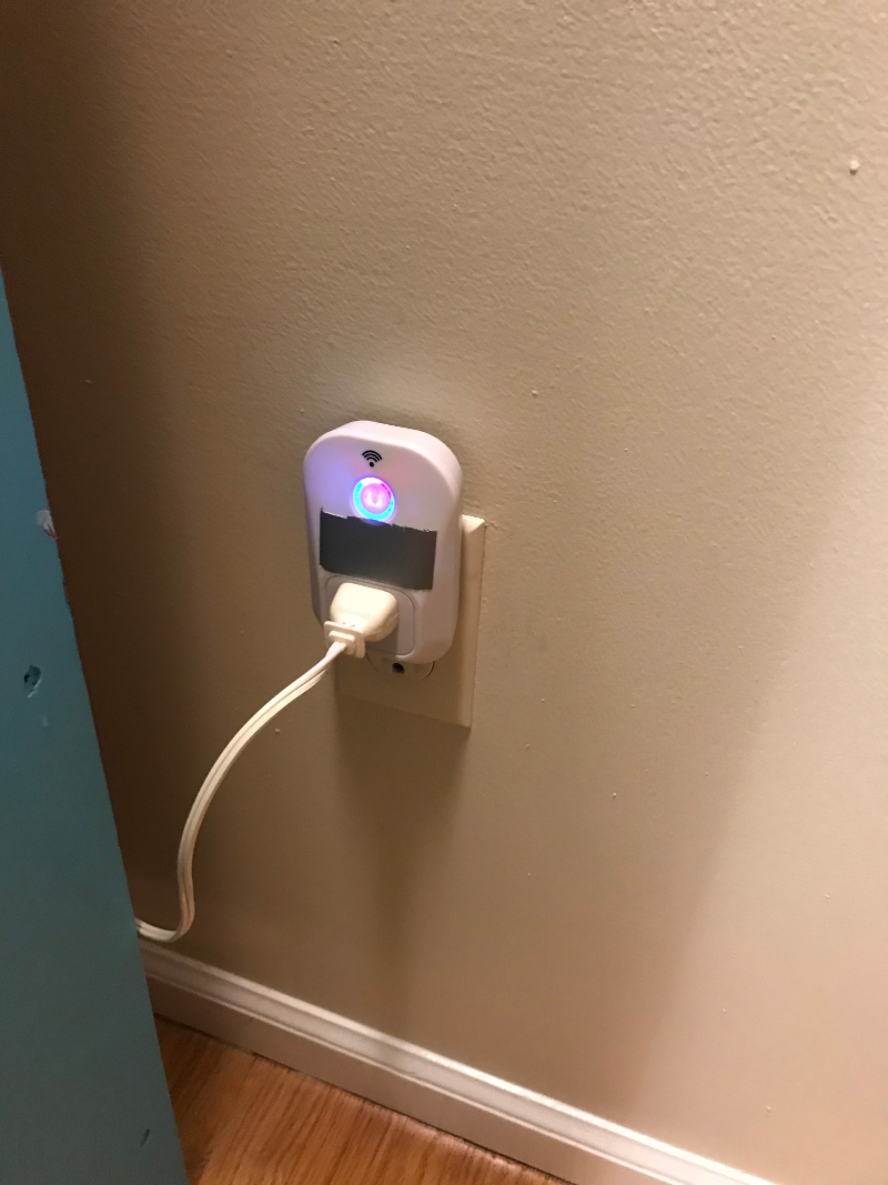
Wifi outlet
These came programmed to be controlled by an android or ios app, but I try to avoid giving my wifi password to devices unless I can program them myself or trust them to be updated regularly. Besides, it just seems crazy to me that a request to turn on a light in my house would ever need to leave my local network.
The only ESP-8266 module I’ve ever used is the beginner-friendly NodeMcu boards. To program them, all you have to do is plug them into a computer with a mini USB cable. I was nervous about whether I’d be able to figure out how to program a less beginner-friendly chip already mounted on a larger board.
When the wifi outlets came, I cracked one open and saw that I was looking at close to a best-case scenario. One of the well-known ESP-12 modules was mounted on one corner of the board, nicely labeled and with a wide margin around it, making it fairly accessible to probing. I didn’t know how I was going to reprogram it, but I didn’t see any obvious dealbreakers. I also noticed that many of the pads on the ESP-12 module did not seem to be connected to the rest of the board at all, which made sense if it only needed to use one or two IO pins. That would also make it easier to reason about.
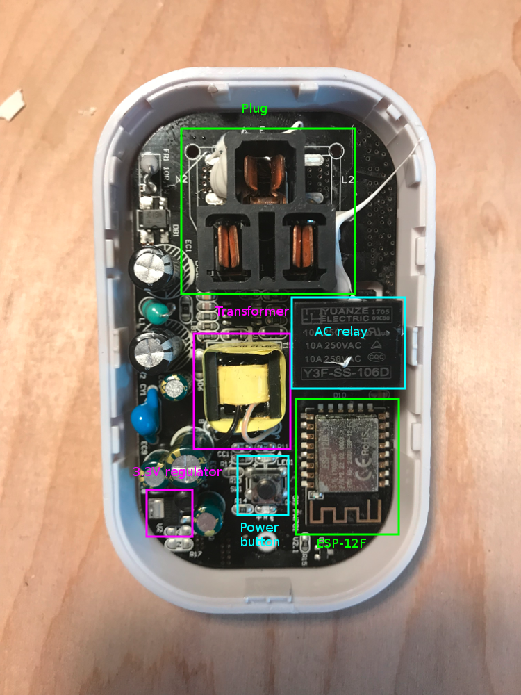
Annotated wifi switch internals
Step one was to figure out exactly how it worked, to ensure that I’d be able to control the relay if I could reprogram the chip. I plugged it in. The single button on the circuit board works as an on / off switch, which was very helpful. From the ESP-12 module diagram I found online, I could identify the VCC and GND pads. As a sanity check, I measured the voltage between VCC and GND, and found it was the expected 3.3V. Perfect! I then measured the difference between GND and each other pad, first with the relay off, and then with it on. This quickly revealed the simple system design. GPIO 12 directly controlled the relay. When it was at 3.3V, the relay was closed and the outlet was powered. When it was 0V, the relay was open and the outlet was off. GPIO 13 was configured as a normally-high input pin. It sat at 3.3V, but if I shorted it to ground, the relay state would toggle. This is how the button controlled the relay.
Now that I knew what I wanted the chip to do, it was time to figure out how to program it. Again, smart, generous people on the internet came through for me. A nicely detailed instructable shows exactly how to wire a freestanding ESP-12 module for programming. I wasn’t about to do surgery on the board, but I had heard that in-circuit programming is often possible, so I was optimistic.
The next challenge was wiring the chip for programming. One obvious choice was to solder wires to the pads and use those. I didn’t like that plan. For one thing, I’m not very good at soldering. For another, the pads are both very close to each other and also (on one side of the chip) close to the plastic housing. I would not have been able to solder the wires on that side without melting and burning the case. Finally, if I was able to reprogram this device, I’d want to reprogram many of them, so I wanted a non-destructive way to reprogram them quickly and reliably.
I’d heard of something called a “bed of nails” programming device, which is a special programming or testing apparatus consisting of a flat board with special spring-loaded pins sticking out of it. When a circuit board is clamped down onto the bed of nails, the spring-loaded pins make contact with test pads on the circuit board, allowing the user to program or test the circuit[0]. I figured that I would be able to 3D print something that would allow me to use the bits of breadboard wires and hookup wire I already had available as a rudimentary bed of nails.
This was my introduction to just how demanding the tolerances for electronics really are. I iterated through 12 different designs for my bed of nails block. First, I thought I could use breadboard wire that already had little pins at the end. But between the varying lengths of the pins and the need to angle the wires in a fan to account for the thickness of the insulation, this failed quickly. Next I started using single-strand hookup wire. Again, any design that relied on the length of the uninsulated tip of the wire proved too unreliable. Finally I tried a design with two tiny holes for each wire, so that a loop at the bottom of the block would contact the pad. Even this was too uneven for all the necessary wires to make contact at the same time.
Many, many iterations
Another issue I ran into was the precision limits of my 3D printer. The holes for the wires needed to be around 1mm. The nozzle on my 3D printer is 0.4mm. In practice, this means that the “slicer” program that generates the path for the 3D printer has a much larger influence on the eventual object than what is specified in the 3D model I try to print. It was a process of trial and error right at the edge of the printer’s capabilities to determine the exact settings that would work. In the end, I created a profile of printer settings specifically for this job, featuring extremely low speeds and a moderate-but-not-too-fine layer height. Using these settings increased the time to print a small block by a factor of about 12, from 5 minutes to just over an hour, but gave me the extra precision I needed.
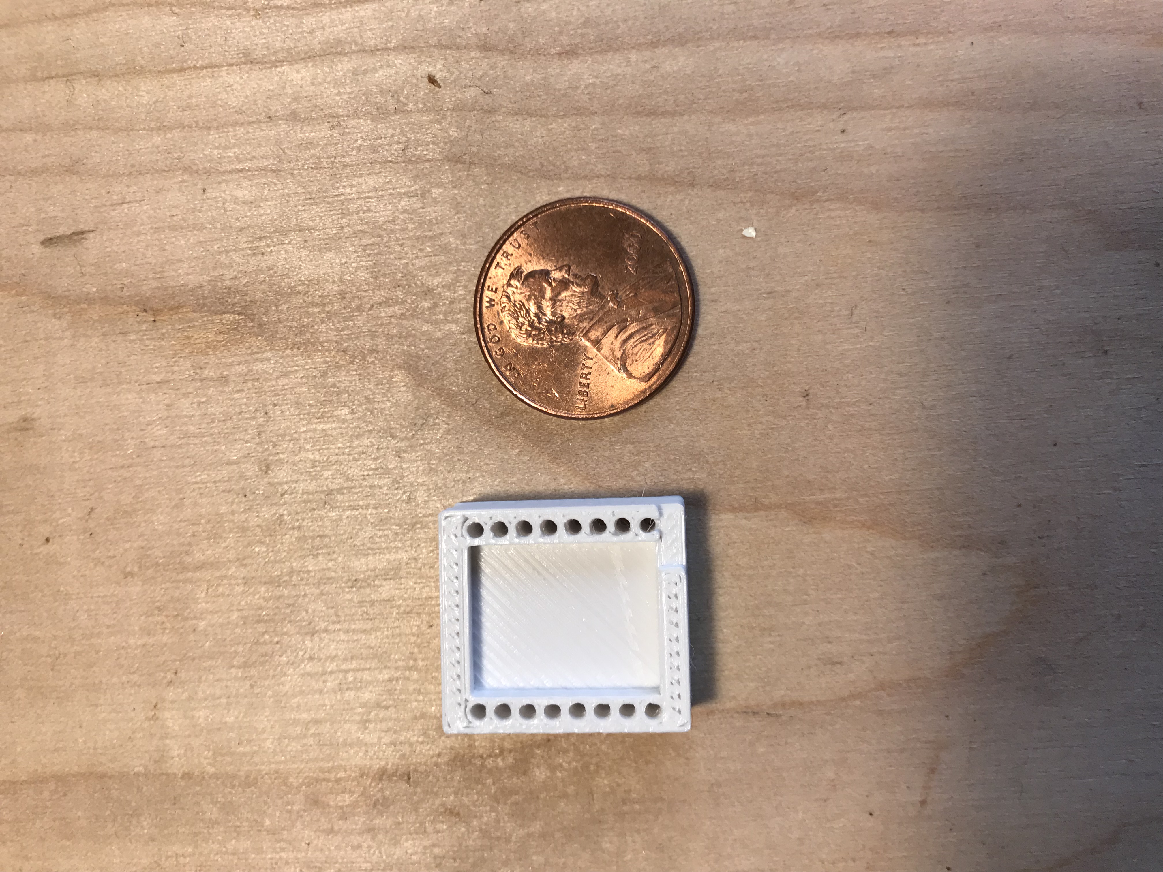
Print time: 1 hour
My last attempt at programming before I gave up on hookup wire was with the block that held tiny loops of wire onto the pads. This at least came close enough to working that I was able to test the programming process. Unlike the development boards I was used to, which can be programmed with a USB cable and a computer, the ESP-12 module lacks the special chip that converts the USB protocol spoken by the computer to the serial protocol needed by the chip. This means that you need an intermediate chip to perform this function, and you need to wire it into a circuit with the chip you want to program. This programming chip also allows you to listen to any messages the chip might send out. There were a few times when I was able to pick up garbled signals on the serial line when I reset the chip. Even though it wasn’t actual text, it made me think I was on the right track. I also learned that the power supplied by the programmer was insufficient to reliably power the chip, so I had to use my bench power supply to feed 3.3V to the ESP-12 and the programmer.
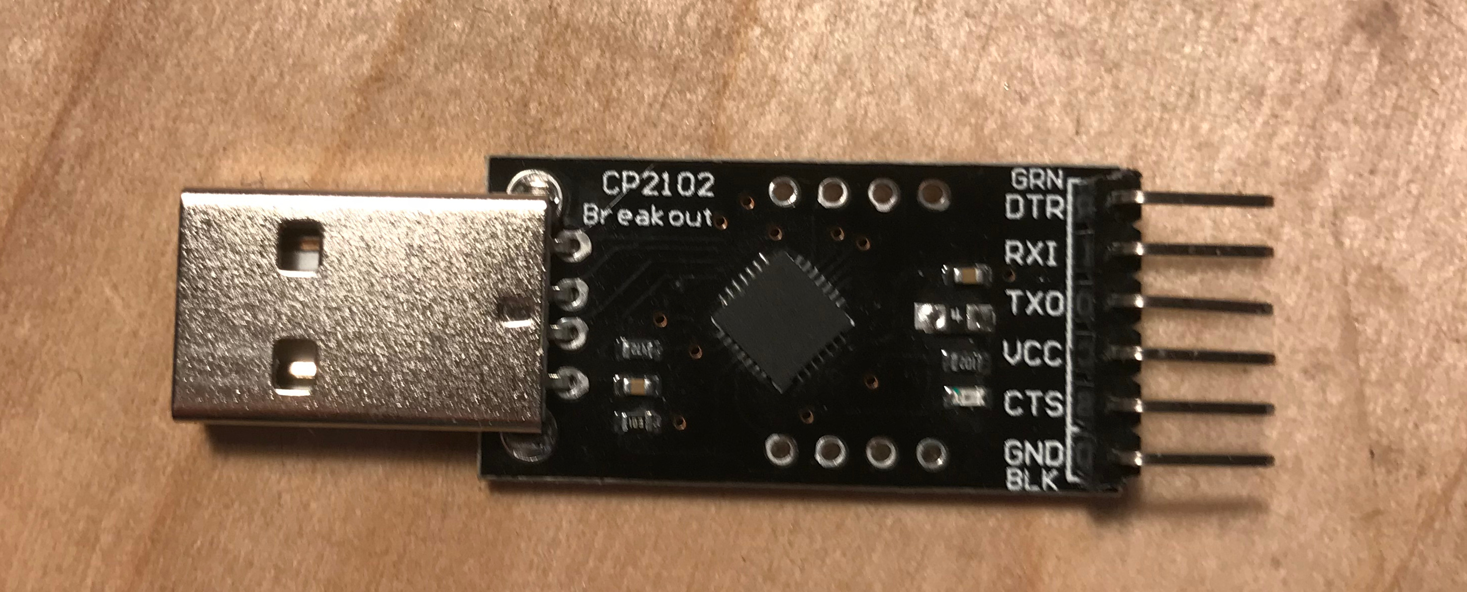
Programmer chip
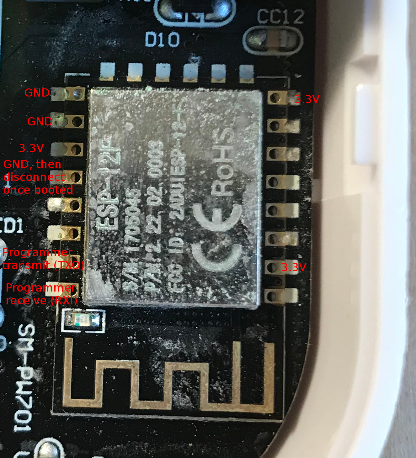
ESP-12 connections for programming. Labels are what the pins should connect to, not what they are.
When I had tried and failed with every configuration I could think of with the materials I had on hand, I went back to researching existing designs. It was then that I discovered “pogo pins” which as the name suggests are small, spring-loaded pins used in professional bed of nails testers. They’re fairly inexpensive–I got 100 in the size I needed for about $12 including shipping without looking too hard for deals.
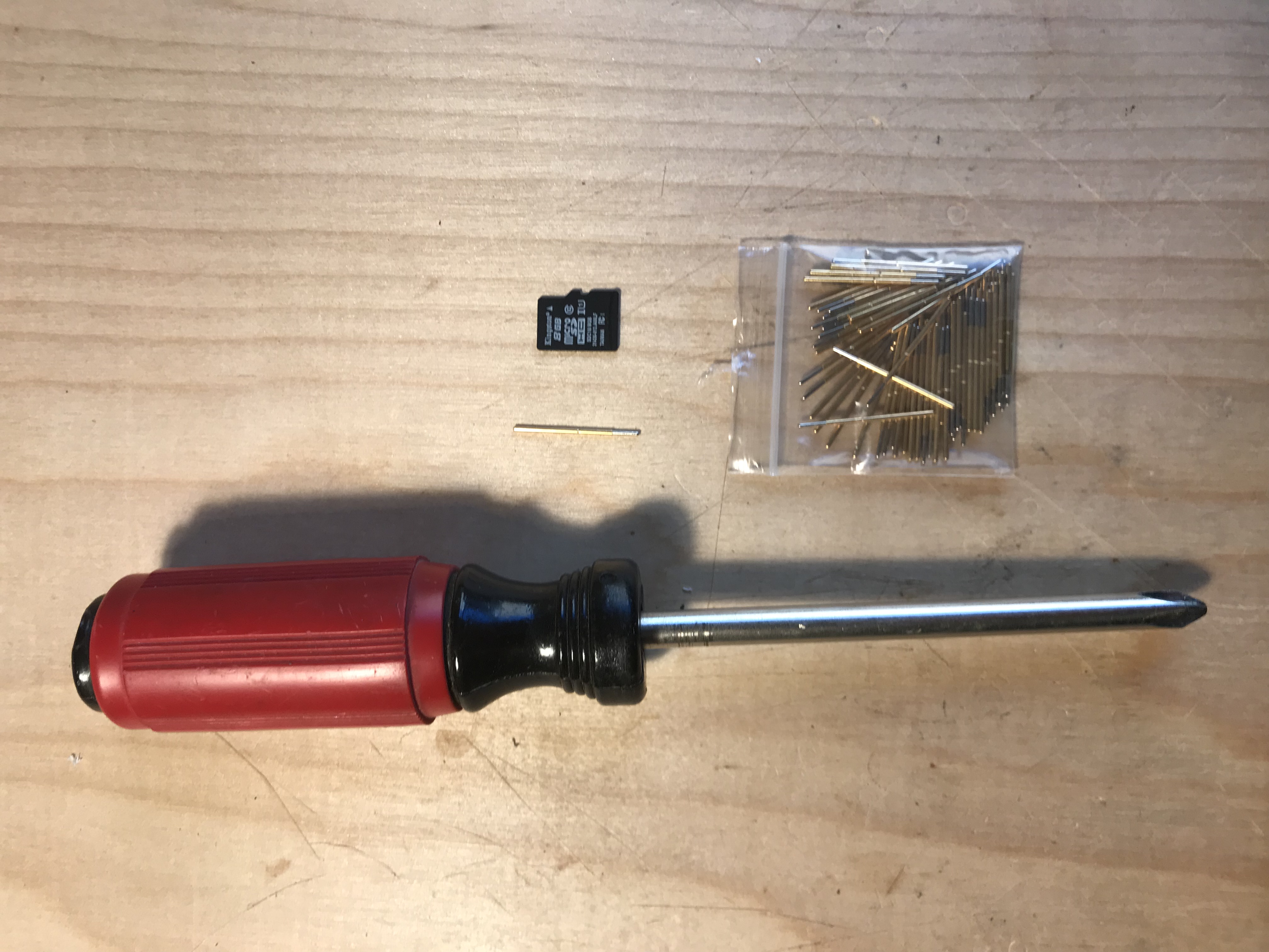
100 count pogo pins
When the pogo pins arrived, it was 2 weeks after I had first started this project, and I had been slowly ramping up the seriousness with which I was approaching the design. At the beginning I was focused on finding quick wins, and I had been rewarded by learing a lot about the circuit layout and programming requirements in a very short time, but had no luck with the actual programming. Now I was ready to drop into a lower gear and plan a little more carefully to ensure a result.
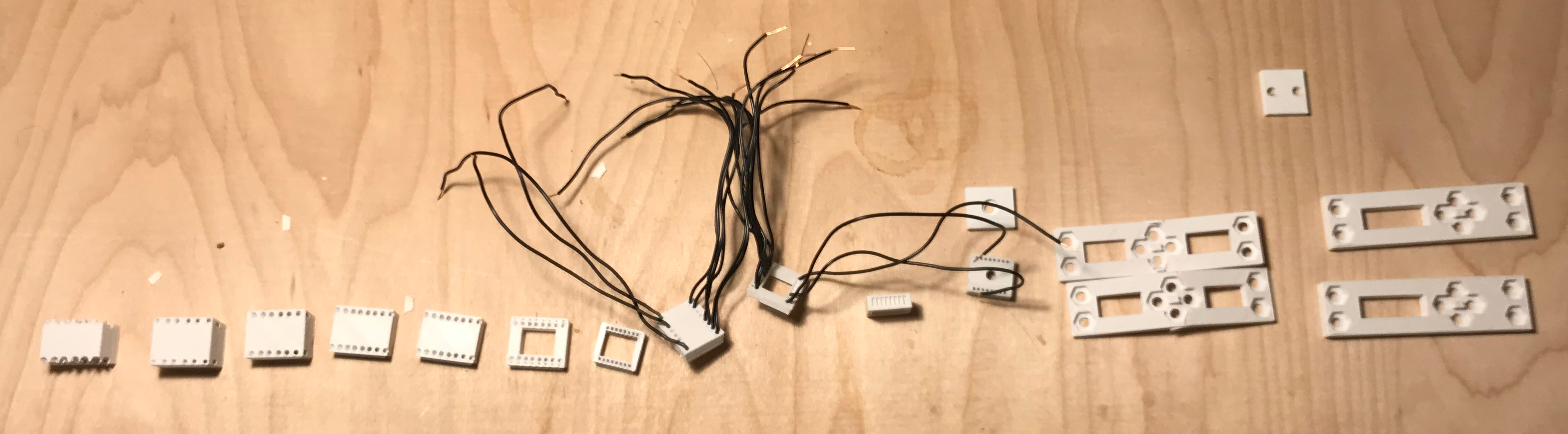
I settled on a design based around a small assembly in which I soldered one pogo pin to a length of hookup wire, then covered the joint in shrink-wrap insulation. On the other end of the wire I attached a female Dupont connector. Making 16 of these small assemblies took about 2.5 hours, but at the end, when I tested them for continuity from the spring-loaded tip to the end of a wire attached to the Dupont connector, I was confident that I had the building blocks of a reliable system.
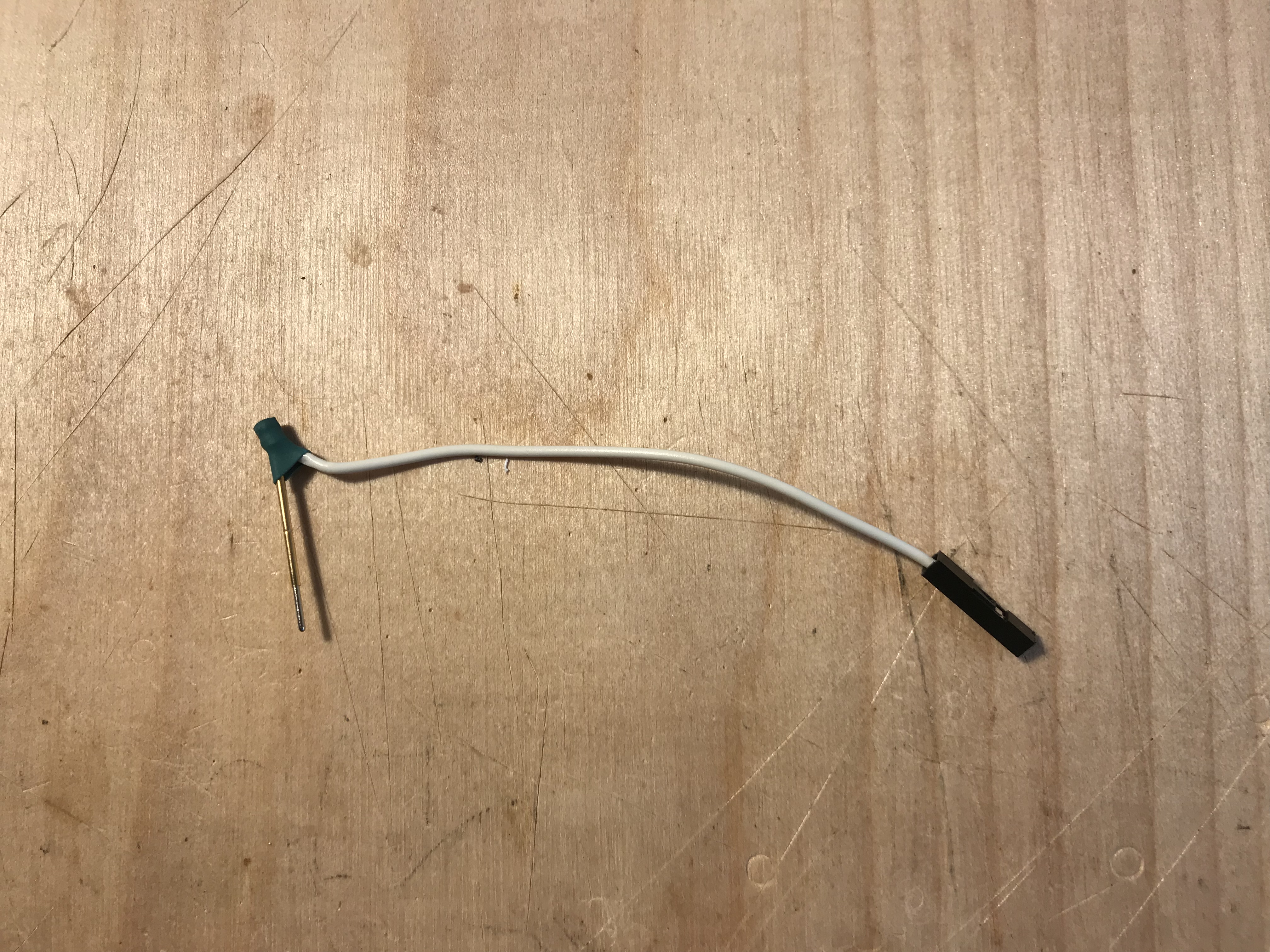
Pogo pin, wire, and Dupont connector
A few more experiments began to suggest the best-yet design for the bed of nails. It would use a block that fit exactly around the ESP-8266 chip, with holes guiding the pogo pins down exactly onto the pads. Surrounding that would be a pair of plates connected by screws, so that the whole system, relay and all, could be held in place and the pins clamped down onto the pads to ensure a good connection.
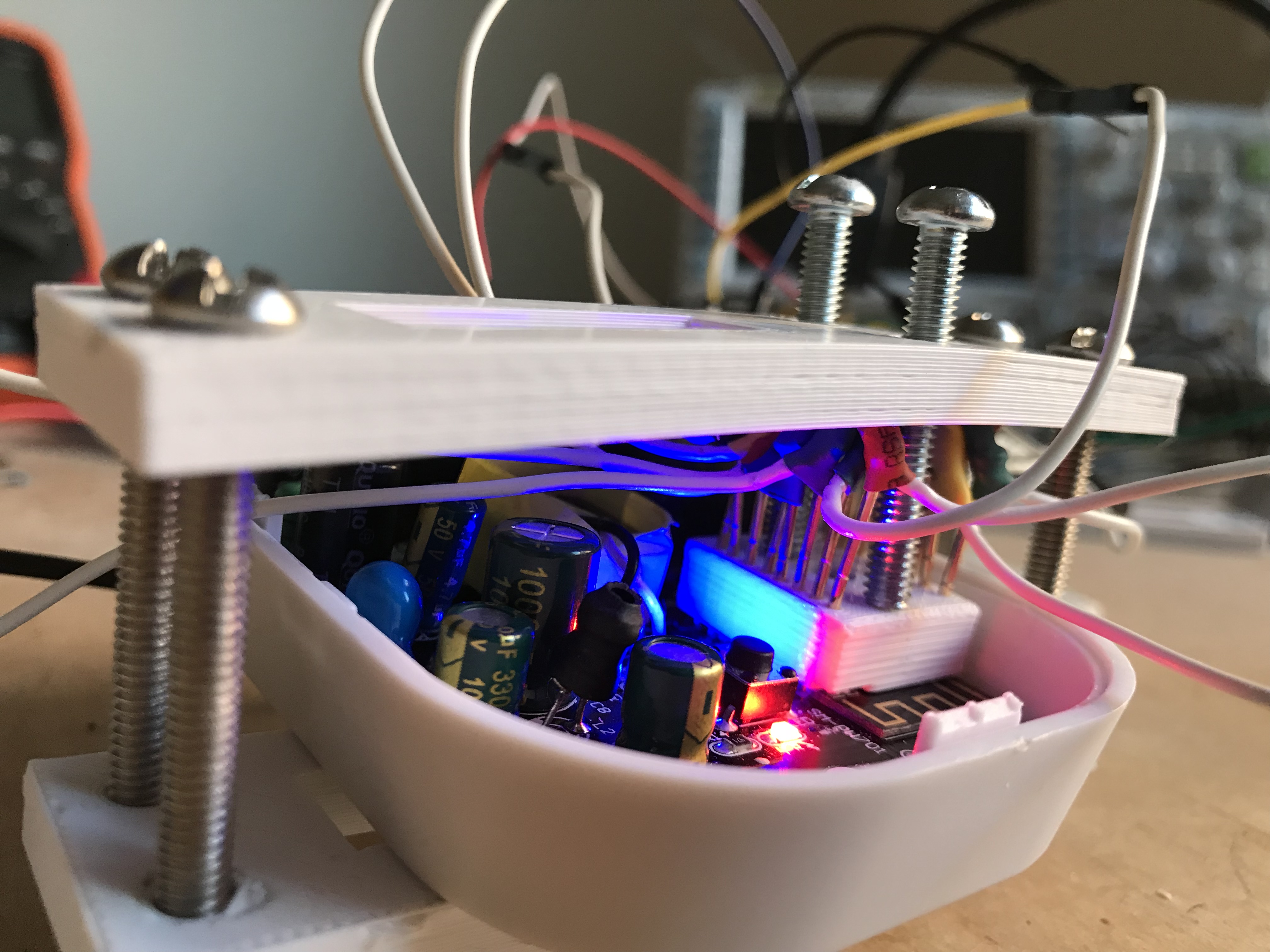
Clamp ensures a good connection, middle screws press down guide and prevent breaking pins by overtightening.
Finally, I was ready for a test. Previously, I had used the reset pad as a test method. I knew that shorting the reset pad to ground should have made the board reset, which looked like a few flashes of the blue onboard LED followed by a blue pulse. But now, when I grounded the reset pin, a red LED came on, and none of the blue ones did. By trial and error, I realized that if I did not make the specified connection between GPIO 16 and ground during startup, the regular reset would happen. But if GPIO 16 was connected to ground as instructed, only the red light came on. When I looked back at the instructions, I realized that this was good news. The reason that GPIO 16 is supposed to be held low is that booting in that configuration puts the chip into programming mode. What I was seeing was that the chip was ready to be programmed.
I hooked up the bed of nails to the chip again. I hooked up the wires to the programmer. I hooked up the programmer to the computer. I had a small test step that “blinked” GPIO 12– the relay control pad–on a two-second cycle. I clicked to program the board, and I almost couldn’t believe it when the upload proceeded smoothly and finished successfully. When I looked over at the board, the red LED that mirrored the relay state was slowly flashing on and off. I put the plastic cover back on, plugged in the relay, and plugged a light into it. Click. The light went on. Click. The light went off. Click. Click. Click. I just watched it for a while. Then I ordered a few more relays :-).
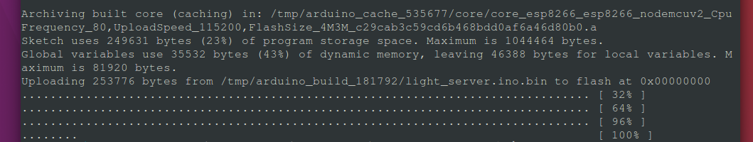
Success after 3 weeks
And the best part?
Much better
(0) This instructable for a bed of nails tester for a 3D printer circuit board demonstrates the principle nicely.